High-pressure coolant system development
At Müller Hydraulik, we primarily develop cooling lubricant systems, chip conveyors, combined systems of both or matching cooling systems for certain machine tools of our partners in the machine tool industry as standard systems with series character. The modular principle for the multiple use of certain industrial standard components, as well as special components developed in-house, plays a decisive role in this. These developments are reflected in our standard products combiloop CL1, CL2, CL3 and CL4, as well as in our chip conveyors chipstream CST1 and CST2, and combistream CS3 and CS4.
Nevertheless, we still have a very high level of development expertise for special systems that are used, for example, in the test laboratories of tool manufacturers or for special machining applications. Sometimes standards are generated from special projects. However, this is not always the goal.
What does the development process at Müller look like and what does it mean for you?
- Individual support from project engineer on acceptance of specifications
- Fast and target-orientated project management
- On-site visit usually a standard
- Use of standard components means high availability of spare parts worldwide
- Four-phase development: everything from a single source!
- Functional testing on high-performance test benches at our premises
- Best possible integration into the machine tool
- Multilingual documentation and customer support
- Commissioning possible on site at the end customer's premises
Four new system development phases to success:
- Project phase:
In the first step, we analyse the specific problem. In this project planning phase, we derive and define the key performance attributes. At this stage, we take into account any usable standard components for an economically viable design and an energy-efficient system, e.g. by using identical parts or assemblies. At the end of this phase, we prepare the quotation.
- Design phase:
In the second phase - the design phase - the specific technical concept for solving the problem is developed. As a partner of renowned component manufacturers and as our own series manufacturer, we integrate the latest technologies - but always in very close alignment with the specified performance profile. Once the basic technical framework, including the parts list, is in place, it can be realised as a 3D model using CAD.

Examples of individual high-pressure coolant systems

In the following, we would like to present three successful customised high-pressure coolant systems.
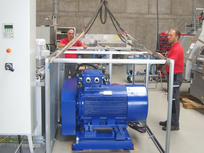
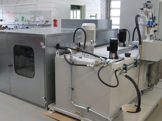
Development example 1
A renowned manufacturer of tools requires a complex high-pressure coolant system with the following characteristics for its research laboratory:
- 1000 bar high-pressure unit, 2000 litre steel tank
- Self-cleaning filter 40 µm with sludge box for 120 l/min
- Ultra-fine filter for maximum pressure
- Pump configuration:
- 50 l/min at 1000 bar
- 29 l/min at 70 bar
- 40 l/min at 5 bar
- 75 dBA noise level via sound insulation
- Prepared for cooling via plate heat exchanger
- Electrical control (Profinet) with frequency converters
The control unit was very complex and the sensors to be installed were correspondingly elaborate, as the customer wanted to be able to determine the pressure and flow rate of the mould to be tested at any time during the test runs, as well as the temperature conditions.
Realisation:

| Feature | Design |
|---|---|
| Tank and filtration | Capacity: 1500 litres Filtration:
Features:
|
| Conventional coolant supply | a) Coolant pump
b) High pressure pump (70 bar)
|
| High pressure | High press 1000 bar
|
| Cooling unit | Systemic preparation for clean tank for possible subsequent retrofitting |
| Electrical control system |
|
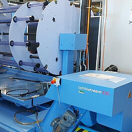
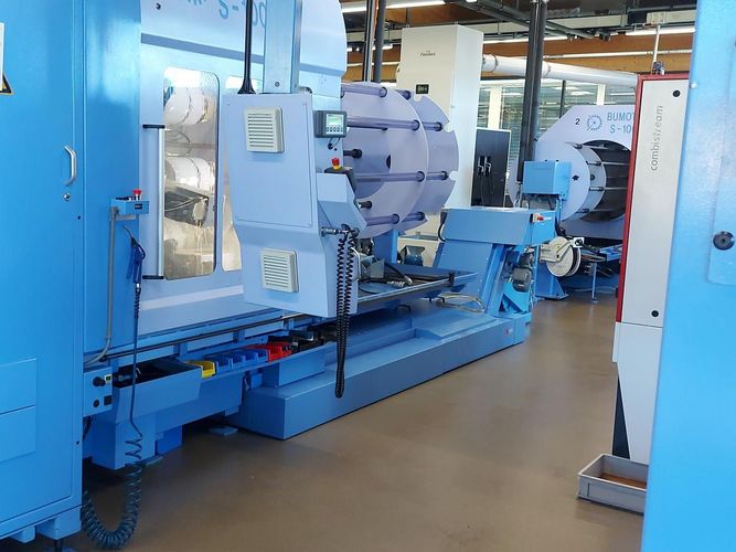
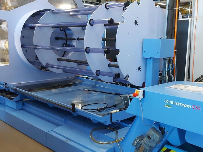
Development example 2
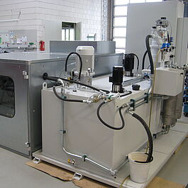
Our customer has developed a multi-spindle machine tool with a very deep machine bed. Extremely high chip volumes, consisting primarily of milling chips and a very high flushing capacity, had to be made process-reliable. We were commissioned to develop an overall concept for the machine, consisting of a chip conveyor and coolant system with the following characteristics and general specifications:
- Voltage 3~/PE 400V / 50Hz
- Dimensions (LxWxH):
- Tank/chip conveyor: 4270x1700 (2265 incl. pipes )x1135 mm
- Paint finish: RAL7043 structure
- High pressure unit: 2200x789 (917 incl. handle and valve outlets)x2000 mm
- Surface treatment: RAL7043/RAL7035/RAL6037 structure
- Discharge height chip conveyor: 525 +/-25 mm
Realisation:

| Feature | Version |
|---|---|
| Low pressure | 2x 110 l/min, pmax = 5.5 bar |
| High pressure 1 |
|
| High pressure 2 (high purity tank) |
|
| Cooling |
|
| Lubricant | Cutting oils |
| Viscosity recommendation | Machining oils 15-22 mm²/s; deep drilling oils 5-8 mm²/s |
| Tank system | Two-chamber tank system with cascade guidance for suction protection |
| Chip conveyor | Müller BK31 system consisting of a working chamber conveyor as a scraper belt conveyor with two top-mounted slotted screens in a specially aligned geometry and a tank bottom cleaning system |
| Suction | from a protected area |
| Return flow | Only filtered medium (full-flow filtration) |
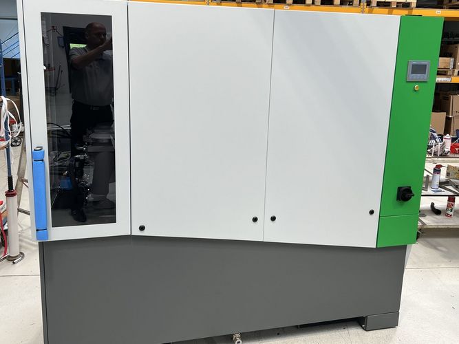
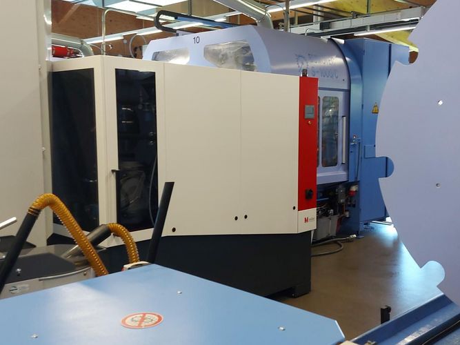
Development example 3
A renowned manufacturer of sliding headstock automatic lathes starts a development project with various partners to develop its own bar feeder customised to the machine tool with the option of fully integrating a high-pressure system. Our task in the team was to develop the high-pressure system in such a way that it could be supplied as an option should the end customer require a high-pressure system.
During the realisation phase, it was then decided to design the high-pressure system in such a way that it would also serve as a support for the loader in the integration area. This ensured a high degree of flexibility in order to fulfil the customer's various configuration requirements.
Characteristics and general specifications:
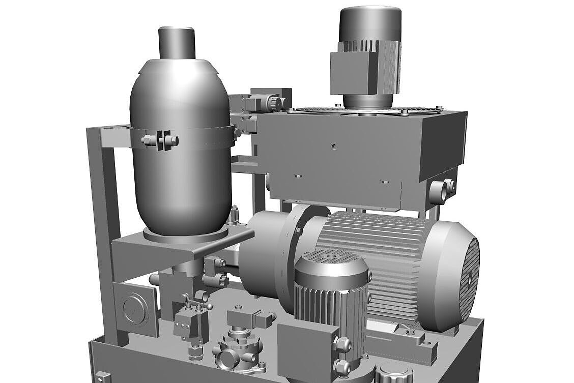
- Stationary high-pressure unit can be individually integrated into bar feeders
- eco+ Dynamic Power Concept
- Dimensions (LxWxH): 1735x665x1070 mm
- Colour: Blue violet / special light grey textured paint
- Areas of application: Early chip breaking, spindle flushing, deep hole drilling up to 0.6 mm and 10xD when using single-lip drills. All chip types. Normal degree of machine contamination. Brass and aluminium should be machined in conjunction with automatic filters.
Realisation:


| Feature | Version |
|---|---|
| High pressure |
|
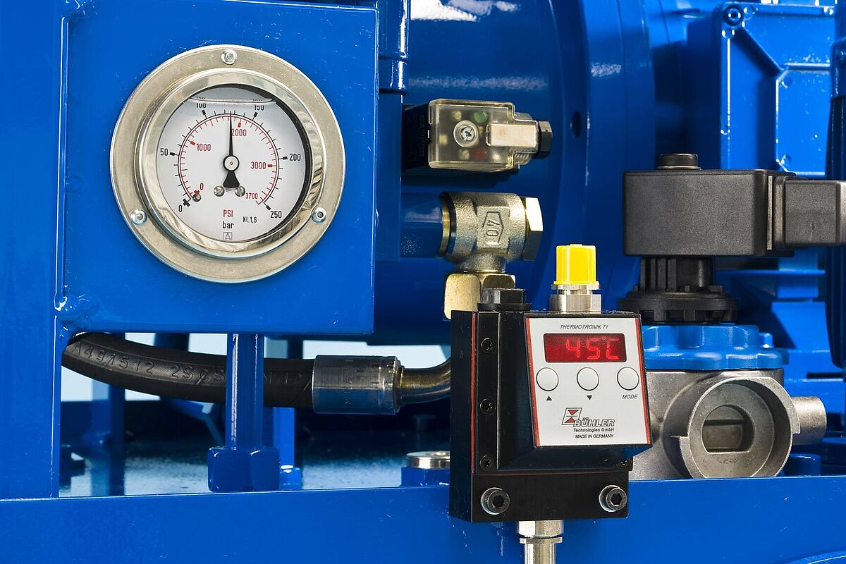
| Outlets | 8 (switchable, 1 of which is adjustable, 5..25 bar) |
| Cooling |
|
| Lubricant | Cutting oils |
| Viscosity recommendation | Cutting oil 15-22 mm²/s; deep drilling oil 5-8 mm²/s |
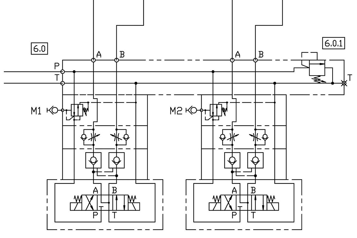
| Function and description |
| The combiloop high-pressure unit consists of a 200 litre clean tank with integrated functional unit. The system is fully integrated into the bar feeder. A pressure-regulated pump is used to generate high pressure, which provides the consumer with exactly the volume flow required at the set pressure. This enables efficient energy utilisation and avoids additional heat generation (eco+). The desired working pressure is infinitely adjustable. The cooling lubricant reaches the consumers in a targeted manner via a direct or switchable high-pressure outlet. A flow monitor is installed as standard. This continuously monitors the flow of cooling lubricant and can trigger an alarm if the flow falls below a minimum quantity. The system is designed as a stationary unit. A filter feed pump draws cooling lubricant from the machine tank and feeds it into the clean tank via a self-cleaning automatic filter. The automatic filter also cleans the machine tank during off-peak times. The filter is cleaned in the sludge box with filter basket integrated into the system. This must be cleaned by the machine operator from time to time. Using the predefined pressure levels option, specific pressures adapted to the machining process can be called up via the machine programme. With the optional plate heat exchanger, the cooling lubricant can be cooled down and the temperature of the cooling lubricant kept stable within the scope of the technical possibilities and prevailing ambient temperature conditions. The medium is cooled continuously (full and bypass flow). A factory-fitted cooling water connection is required for this. The system has an electrical control system, which enables autonomous operation. A 46-pin Harting plug forms the interface to the machine. The power supply is connected to a terminal. Electrical connection: 400V 3~/PE 50Hz. |
| Components of the integrated high-pressure system |
|
